
|
Digital Pin Display, prospect and product specification
April 7, 2003 Mediatechnology masters programme, Leiden Institute of Advanced Computer Science, Leiden University |
- Digital Pin Display, pictures - Digital Pin Display, movie |
| introduction | For a long time, I have been fascinated by the so-called Pin Art unit, also known as the Pinpression. This device has the ability to store 3D images by manually shifting small pins mounted on a surface. You can store your beloved's face or hand in the device and put it on a bookshelf or mantelpiece. However, the device has one major disadvantage; when you want to display another image, the previous image gets lost forever. This notion of pins representing shapes and forms lead to the idea of building an automated device, the Digital Pin Display, which could display stored images by shifting pins. Images can be stored in a databank and can be displayed at any desired moment. Making the display both an input- and output device might have been possible, but was not the aim, since building it as only an output device would be complicated and costly enough and secondly, various 3D input devices have already been developed by several manufacturers. |
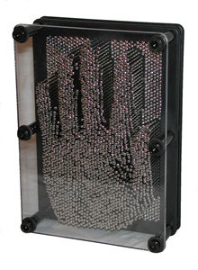
Pin Art or Pinpression |
concept and aiming
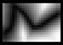
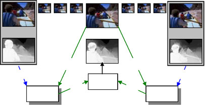
Original image 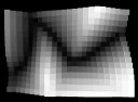
Image extruded by Adobe's Photoshop 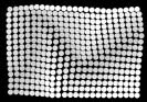
3D simulation of Digital Pin Display |
The ambition was to build an automated device, which can transform an
image to a physical 3D output. An image is (in most cases) a 2D representation
of a 3D world. This 2D picture contains a lot of 3D information. The human
eye together with the brain has been trained very well to extract depth
from a 2D image, just because one recognizes the objects, and knows how
these look in the 3D world.
A computer can also be programmed to extract 3D data from 2D images: Converting a flat image into spatial data points. This is called extrusion. Extrusion can be done in various ways, depending on the intelligence of the software
This bright parts are closer than dark parts is also the main principle behind the Digital Pin Display. Greyscale images are stored in a databank, and the level of luminance is representing the extension of the pins. Major electronics companies are working on methods to convert 2D content for 3D television for the future. Also depth tweening can de used for extracting 3D data by using the difference between key frames. In all 2D to 3D conversion software level maps are used to store the 3D information, in most cases a regular greyscale picture since this is also a kind of level map. This means grey levels are a solid carrier for 3D data. The aim of the Digital Pin Display project is twofold:
Depth tweening using grey levels as 3D data carrier |
|
| procedure |
A commercial Pin Art or Pinpression unit (7" x 5") beholds 2215 pins
or more. In case of an automated device, such an amount of electrically
controlled pins would result in the device being:
|
|
| scale | To make the Digital Pin Display relate more to the human body than the regular Pin Art unit, I have made it larger then the Pin Art device, but not too big. If the display would have been too big, the viewer would have to be at very large distance. A good size for the Digital Pin Display appeared to be 52.5 x 35cm (3:2). | |
| pins and display |
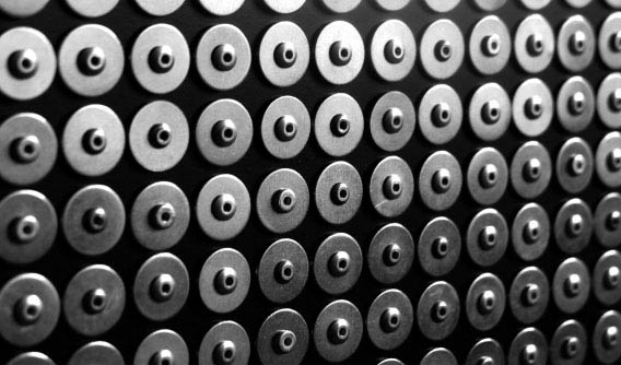
Because a simple pin display (with a smaller amount of pins) would have taken the same research and testing as an extensive display (mechanically), I started with a relatively simple display of 24 x 16 pins (384 total), which could be extended at a later moment if required. Why 24 x 16? 16 pixels is a minimal height (or width) to be able to display any kind of words, pictograms etc. In fact, this is already rather limited. An standard icon on a computer display has already a resolution of 32 x 32. There are also smaller versions of 16 x 16, but these are more difficult to recognize. The scale of the display would be 3:2. Therefore a resolution of 16 x 24 has been chosen. A 16 x 24 unit seemed to be rather doable. Starting from 35 x 52,5 cm this resulted in a pin size of 2 cm, leaving a small distance between every pin: 35 (cm) / 16 (pins) = 2.19 cm Should these pins be round or square? Considering production time, round pins was much easier. Round holes can be drilled and round pipes are more common than square pipes. 3D simulation tests pointed out that it didn't really matter whether the pins were round or square for visual perception, as long as they were not solid but with a wider cap mounted on a thin pipe. The pins on the Digital Pin Display are made of aluminium with zinc-plated rings and the top layer of the display plate in which they are mounted is made of black HPL (High Pressure Laminate) from ARPA, Italy. This appeared to be a very good combination since a lot of the dark in the 3D images is coming from the black plate and the reflection of this plate in the pins. |
|
|
||
| mechanics |
To use as little electronics and mechanics as possible, yet have a fast image display, I chose for a system which controls the pins column by column. To control a column of 16 pins you need subsequently 16 elements, which can shift the pins. For the shifting of the pins I chose for servomotors, since these are very accurate. With servomotors and the hardware, which controls these, the pins are controllable with values from 0 to 127. Whether a resolution of 128 would have been necessary is not really important, but for sure it is enough. The column of servomotors had to shift to the left and right along a rail to be in the right positions. For this a stepper motor seemed most appropriate because servomotors have a small turn range (90°). The disadvantage of stepper motors is that they are less accurate and have lower speeds. Initially I wanted the pins to be shifted back by the servo's to the starting point when an image is completed, but this seemed like asking for trouble on such a small scale: jamming parts, damages etc. For that reason the total display needs to be re-setted. This was possible in various ways, for example by pushing them back with a plate. Finally I chose for the same way which is used to clear the Pin Art or Pinpression, which is by far the fastest, most simple and clearest way: the display turns 90° which makes the pins fall inside the display plate. The pins just have to be pushed out to compose the image. This has an advantage of time, but I asked myself if it would be visually pleasing if the display would have to turn over. I was overseeing one thing: it could produce a most lovely sound. The turning of the display is controlled by two stepper motors, and the display has a electromagnetic lock to prevent it from turning when the pins are pushed. In this way the controlling of the pins is relatively simple: 16 units of servomotor, gear and serrated bar are vertically mounted on a stepper motor controlled rail. The stepper motor shifts the rail until the serrated bars are in line with the desired column of pins. Now, turning the servomotors will shift the bars. The bars then shift the pins as they make contact. The rail moves to the next line of pins. 
Parts and description, top view |

stepper motor 
servomotor 
resetting the display 
controlling the pins, top view 
servomotor with gear and serrated bar, side view |
| electronics |
The stepper, servomotors and also the display lock had to be controlled by a computer. For this I integrated two circuits, designed and developed by employees of the electronic workshop of the Royal Conservatory in The Hague, onto one circuit board.
|
|
Circuit diagram |
||
|
I wanted to use the MIDI (Musical Instruments Digital Interface) protocol
to control the motors since the application Max by Cycling '74 has the
ability to send MIDI events in a rather easy way. Other options were to
use USB, RS232 or parallel port, but these are much harder to implement.
MIDI also made the Digital Pin Display controllable by different computer
platforms varying from an old Atari 1024ST to the fastest PC or compatible
with any MIDI sequencer.
The first circuit was the MIDI to servomotor interface. Except for the program of the PIC (Programmable Integrated Circuit) you can buy everything in a good assorted electronics store. The second circuit, the MIDI to stepper motor interface was much more difficult to build, especially since it was built onto the same circuit board as the servomotor controller. Since it has a shared power supply and ground, a small mistake makes both the circuits defective and errors are hard to detect. |
||
|
I also wanted to have feedback from the display, which could have be
important for status checks. For that I used some external switches and
heat detectors connected to a regular USB keyboard. The computer software
easily recognizes these key contacts, so now the program gets information
about the position of the display, the servomotor rail and the temperature
of the double H-bridge processors which control the stepper motors.
The electronics were to be integrated into the Digital Pin Display, but for several reasons I decided not to do that. The circuit boards are rather vulnerable for vibrations, especially the stepper motors are not doing these circuits any good, and also the looks of the electronics are not as they were planned due to various modifications and regulation systems against overheating. Therefore, the electronic subsystem is housed outside the DPD in separate housing. |
||
| electronic circuits |
MIDI to stepper motor interface 
MIDI to servomotor interface |
|
| images |
Though the initial meaning was to try to display real life images on
the pin unit, the initial pointed out that abstract relief-like images
were much more interesting. The pictures needed to be simplified images
like pictograms, possibly text or geometric patterns...
The display can be used for all kinds of images. From stills from a digital video camera to live generated images. Just the resolution of 24 x 16 pixels provides the limitation of the system. For demonstrational reasons I have made a folder with different types of images. | |
| software and user interface |
To maintain the software fairly simple I decided to use the application
Max by Cycling '74. Max is a visual development environment for real-time
interactive music and media. You make programs by wiring "object" boxes
and user interface components together with patch cords.
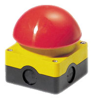
The software has to read images out of a databank and send MIDI data to the circuit boards, which control the display. There is a limited user interface, but that has been developed for demonstrational purposes. Since people were asking me for interaction with the Digital Pin Display I decided to add the ultimate user interface: a giant quiz-like button which sets the software to start making a new picture on the display. Apart from providing some rudimentary user interaction, this prevents the display from wearing out the motors when nobody's there to see it. |
|
| thanks to |
Mediatechnology, Leiden Institute of Advanced Computer Science,
Leiden University:
Maarten Lamers - support, help and confidence for getting me through this process Martine Roeleveld - support Bas Haring - support |
|
|
College of Higher Education of Fine Arts, Music and Dance,
The Hague:
Frans Evers from the Interfaculty Image and Sound - advice and providing facilities Jo Scherpenisse and Lex van den Broek from the electronic workshop of the Royal Conservatory - circuit board diagrams, PIC processor programming and help by building the electronics All the people of the metal and wood workshops from the Royal Academy of Fine Arts - advice |
||
| Dick van Schravendijk, Antwerp - workspace | ||